
What is a DXF file? Using CAD drawings in GIS
An engineer hands you a drawing, and you need it on a map. That hand-over usually involves a DXF file, so this guide explains what the format is, why CAD data behaves differently from GIS data, and how to bring a drawing into GIS without it landing in the wrong place.
Key facts
- DXF is Autodesk's CAD interchange format: it stores geometry on drawing layers with no attribute table.
- CAD drawings usually carry no coordinate system and sit in local units (meters, feet or unitless).
- The binary DWG format must be saved as DXF first for most GIS tools to read it.
What a DXF file is
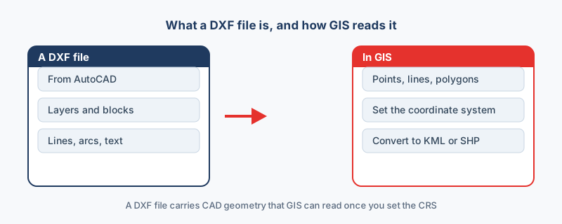
DXF is Autodesk's open drawing format, and almost every CAD tool can read and write it, which makes it the usual bridge from AutoCAD to other software. The file holds drawing elements such as lines, polylines, arcs and text, organized in layers and blocks, so it thinks in drawings rather than in map features. That is why a DXF tends to turn up whenever engineering meets mapping.
CAD and GIS rest on different ideas
CAD and GIS look similar on screen, but the two rest on different foundations: a DXF has layers and blocks where a GIS layer would have an attribute table, so some translation is always needed to get from one to the other. The table shows where they part ways.
| CAD (DXF) | GIS | |
|---|---|---|
| Built around | The drawing | The feature |
| Organized by | Layers and blocks | An attribute table |
| Coordinate system | Usually none recorded | Stored with the data |
| Units | Meters, feet or unitless | Defined by the coordinate system |
The step that matters most
A DXF often uses a local or engineering grid, so its numbers may be meters that sit nowhere near latitude and longitude, and without a coordinate system the drawing lands in the wrong place.
- Find out which system the project used, such as a UTM zone; codes can be looked up at epsg.io.
- Assign that system when you convert, so the numbers get their meaning back.
- Reproject to WGS84 if the destination is a web map or Google Earth.
Convert a DXF to a map format
The conversion runs in your browser with nothing uploaded. Use DXF to KML for Google Earth, DXF to Shapefile for GIS, or DXF to CSV to pull the coordinates into a table. Geometry converts well and layers map to a field, but blocks and styling may be simplified, so check the result in your GIS. MicroStation DGN files convert the same way through the CAD converter; the reader handles DGN V7, so save a V8 file as V7 or export it to DXF first. Background on the format is on the DXF overview.
“The gap between CAD and GIS is the coordinate system. A DXF is precise to the millimeter in drawing space and completely unplaced on the globe until you tell it which CRS it is in.”
Frequently asked questions
I have a DWG, not a DXF. What do I do?
DWG is AutoCAD's binary format and is harder to read directly. Save it as a DXF in your CAD program first, then convert the DXF to the GIS format you need.
What about MicroStation DGN files?
The converter reads DGN V7. Save a V8 file as V7, or export it to DXF, then run it through DGN to Shapefile or the CAD converter.
Is my drawing uploaded during the conversion?
No. The conversion runs in your browser, so the drawing never leaves your machine. That matters for engineering files covered by a confidentiality agreement.
Why does my DXF file appear in the wrong place in GIS?
CAD drawings often use a local or projected engineering grid in meters, not latitude and longitude. If the coordinate system is not set, the drawing lands far from where it should. Assign the correct CRS before mapping.
What is the difference between CAD and GIS data?
CAD is drawing-centric and uses layers and blocks, while GIS is feature-centric and uses an attribute table. Converting a DXF file translates drawing geometry into GIS features, so expect some simplification.